A Brief Analysis on Installation, Usage, and Structural Characteristics of JBK3 Series Machine Tool Control Transformers
1. General
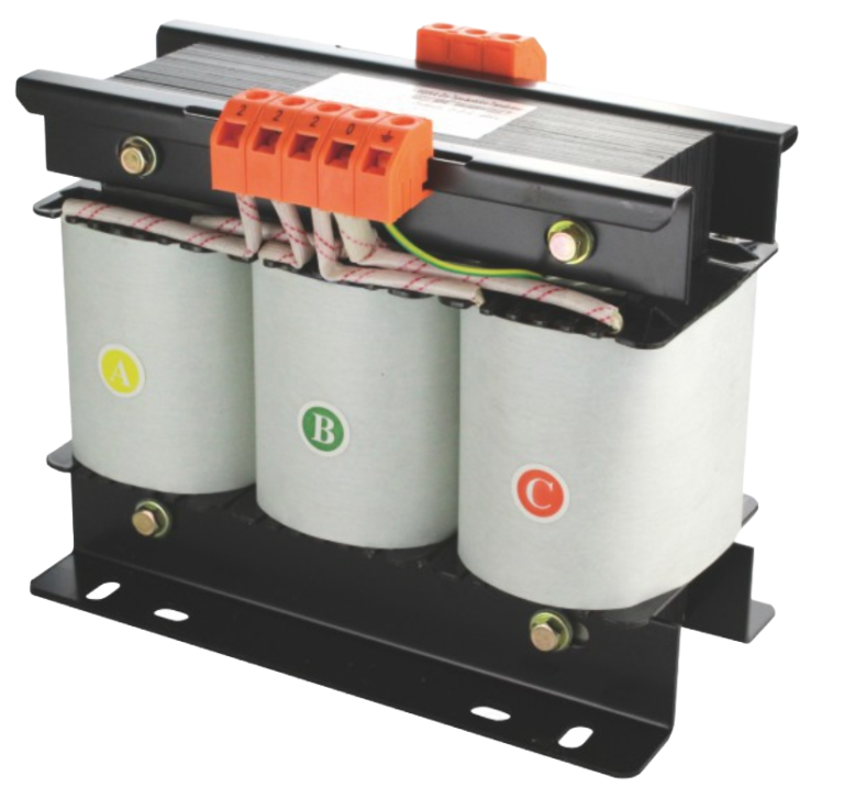
The JBK3 series machine tool control transformers are a new generation of energy‑saving dry‑type transformers developed in China with reference to similar international products (e.g., Siemens samples). They comply with international and national standards such as IEC 439, GB/T 5226, and JB/T 5555. These transformers are widely used in AC 50/60 Hz circuits with voltages up to 660 V, serving as control power supplies, working lighting, and signal lamp power sources for various machine tools, precision mechanical equipment, and automated control devices. Their rated capacity ranges from 63 VA to 5,000 VA, accommodating different load classes of control systems.
2. Structural Characteristics and Manufacturing Advantages
The structural design of JBK3 transformers fully addresses the high‑reliability requirements of machine tool control circuits, featuring the following notable characteristics:
Core and winding materials: The core is assembled from high‑grade silicon steel sheets to minimise hysteresis and eddy‑current losses. The windings adopt an open‑wound, neatly arrayed coil winding method (bobbinless construction), using high‑strength enameled copper wire with a temperature rating of 180 °C and a withstand voltage of 2,500 V, ensuring excellent electrical strength and thermal stability.
Insulation and protection system: The transformer undergoes vacuum impregnation processing, raising the insulation class to Class H (temperature rating 180 °C). This significantly improves the dielectric withstand capability and moisture resistance, effectively suppressing creepage and flashover risks during operation. The terminal blocks feature a protective design, combined with curved washers and captive screws, which prevents inadvertent finger contact with live parts and ensures long‑term reliable tightness of connections.
Multi‑winding configuration: The primary and secondary windings are physically separated. The secondary side can be designed with multiple independent windings according to user requirements for control, lighting, and indicator circuits. It should be noted that when a single winding has a centre tap, the tap capacity is generally less than the rated capacity; only the highest‑voltage output terminal can deliver the full rated capacity.
3. Installation and Operation Specifications
To guarantee safe long‑term operation, the following electrical technical guidelines must be strictly followed during installation and wiring:
Pre‑installation verification: Before installation, carefully check the nameplate parameters (input/output voltages, capacity) to confirm that the supply voltage matches the rated tap setting of the transformer. Inspect all fasteners and connections for any loosening during transport, and measure the insulation resistance (which should be no less than 150 MΩ at normal ambient temperature).
Wiring and earthing: Wiring must be carried out in strict accordance with the terminal markings; the primary and secondary sides must never be reversed. The transformer body is equipped with a dedicated earthing screw and a clear grounding symbol. The enclosure must be reliably connected to protective earth (PE) to prevent leakage current and electric shock hazards.
Environmental requirements: The transformer should be installed indoors in locations free from severe vibration, corrosive gases, and conductive dust. The altitude shall not exceed 2,000 m, and the ambient temperature range is –5 °C to +40 °C. For operation at higher temperatures or altitudes, derating should be considered.
Overload protection: Although the transformer possesses a strong overload capability (capable of withstanding 2 times the rated current for 1 minute), the actual total load must not exceed the rated capacity (in VA). When multiple secondary windings are used, the total load capacity must be calculated proportionally to avoid long‑term overheating due to persistent overload.
4. Application Case Studies
Case 1 – Logic control power supply for a CNC machining center
In the electrical cabinet of a vertical CNC machining centre, a JBK3‑500 VA transformer is employed. The primary side connects to two phases of a three‑phase 380 V supply (AC 380 V). The secondary side is designed with two independent windings: AC 110 V for the CNC system I/O interfaces and contactor coils, and AC 24 V for the machine work lamp and sensors. Through galvanic isolation, the transformer effectively suppresses harmonic interference from the mains, ensuring system stability under frequent start‑stop operations.
Case 2 – Auxiliary power supply for servo drive systems on an automated assembly line
In the servo drive control unit of an automated assembly line, a JBK3‑800 VA transformer is selected as the control power supply for the servo drives. The primary input is AC 380 V, and the secondary output provides AC 220 V for the servo drive control terminals, while an additional tapped winding delivers AC 12 V for signal indicator lamps. Leveraging the Class H insulation, the transformer maintains low temperature rise (controlled within 155 °C including ambient temperature) and low noise (<45 dB) even under continuous long‑term operation in a cabinet with elevated ambient temperatures. This significantly reduces the equipment failure rate in harsh working conditions.